Introduction
The Flashforge M5 Main Board Pin Outs 3D printer is at the forefront of desktop manufacturing innovation, offering a blend of user-friendly and advanced features for new and experienced users. Central to its operation is the main board, a sophisticated electronic system that governs every aspect of the printer’s functionality. A deep understanding of the Flashforge M5 Main Board Pin Outs main board pinouts is essential for anyone looking to troubleshoot issues, perform custom modifications, or enhance the machine’s performance. This article provides an exhaustive exploration of the FlashForge M5 main board pinouts, equipping users with the knowledge to fully leverage their 3D printer’s capabilities.
Overview of the Flashforge M5 Main Board Pin Outs
The Flashforge M5 Main Board Pin Outs acts as the brain of the 3D printer, managing and synchronizing all its electronic and mechanical operations. This board includes the processor, memory, and various connectivity options, allowing the printer to accurately convert 3D models into physical objects. It features many connectors and ports, each assigned specific tasks such as motor control and temperature management. Understanding the Flashforge M5 Main Board Pin Outs main board’s specifications and layout is crucial for anyone attempting diagnostics or enhancements.
Each connector and port on the Flashforge M5 Main Board Pin Outs main board plays a specific role, from powering the machine to transferring data to different printer components. For users interested in the inner workings of their device, knowledge of these functionalities is invaluable. Whether addressing a malfunction or contemplating an upgrade, familiarity with the main board’s complex circuitry is essential.
Detailed Guide to the Main Board Pinouts
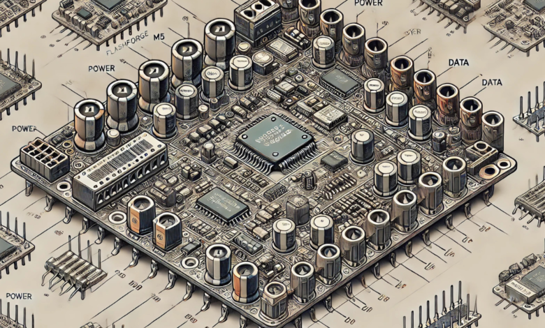
Pinouts are crucial for comprehending how the FlashForge M5 main board communicates with the rest of the printer’s components. Each pin is a conduit, facilitating essential communications between the board and elements like motors, sensors, and other modules. This segment provides an in-depth mapping of the main board, accentuating necessary connectors and their roles. Identifying power connections helps users prevent common setup errors, such as incorrect wiring, which can damage the electronics severely.
Further, we explore the specific types of connectors in greater detail. For instance, the motor driver pins are vital for the precise movement control of the printer’s axes. At the same time, sensor inputs keep track of critical conditions like temperature and position, ensuring real-time adjustments during printing. With a solid grasp of these connections, users can confidently address issues like misaligned layers or temperature inconsistencies without resorting to guesswork.
Practical Applications of Main Board Pin Out Knowledge

Mastering the FlashForge M5 main board pinouts allows users to troubleshoot effectively and carry out modifications that boost the printer’s functionality. For example, knowing which pins manage the heating elements enables users to replace or upgrade these parts to handle a wider array of materials. Additionally, understanding signal connectors can facilitate the integration of extra sensors for enhanced accuracy and reliability.
This expertise also empowers users to perform comprehensive diagnostics. For example, consistent errors in X-axis movement can often be traced back to a connection issue with the motor driver pins responsible for that axis. Identifying and correcting such problems can significantly reduce downtime and resource expenditure typically associated with trial-and-error methods.
Safety Precautions and Best Practices
Handling the electronics of a 3D printer, especially the FlashForge M5 main board, requires careful attention to safety. Before interacting with the main board, it is imperative to disconnect the printer from any power source to avoid electrical accidents. Users should also utilize appropriate tools, such as anti-static wristbands and non-conductive screwdrivers, to protect themselves and the delicate main board components.
Adhering to best practices for electronic maintenance, such as regular inspections and ensuring all connections are secure, also helps preserve the integrity of the main board. These practices prevent physical damage and prolong the printer’s lifespan, ensuring consistent and reliable performance.
Conclusion
Delving into the FlashForge M5 main board pinouts is more than a technical necessity; it is essential for maximizing the potential and functionality of your 3D printer. Whether you are troubleshooting, upgrading, or aiming for the highest quality prints, the knowledge provided here will fundamentally change your approach to 3D printing.
Frequently Asked Questions (FAQs)
Q: What are the most common issues that can be diagnosed by understanding the FlashForge M5 main board pinouts?
A: Common problems include motor failures, sensor errors, and power discrepancies, all identifiable and often resolvable through a detailed understanding of pin connections.
Q: How can I verify that I connect wires to the correct pins without damaging the FlashForge M5 main board?
A: Always refer to the main board’s schematic diagram before making connections, and use tools like multimeters to confirm the function of each pin.
Q: Are there resources available for further learning about 3D printer electronics?
A: Numerous online forums, tutorials, and courses cover the basics of advanced electronics involved in 3D printing.
Q: Can modifications to the main board void the warranty of my FlashForge M5?
A: Yes, unauthorized modifications can void the warranty. Always check the manufacturer’s policy before proceeding with hardware modifications.
You May Also Read: https://topblogbuz.com/the-block-mini-latesthealthtricks-meet/